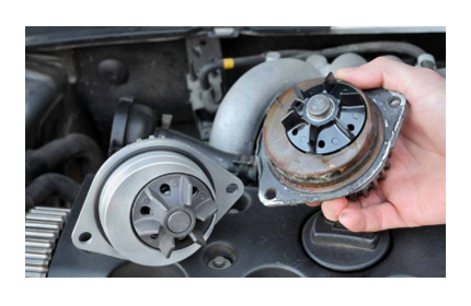
Our automotive single-phase water pump controller solution uses an automotive-grade MCU together with a single Hall sensor, providing a reference for low-power sensored single-phase BLDC motor control in automotive applications.
Key Points
- AEC-Q100 qualified motor-dedicated device
- Single-Hall interface circuit
- Single-sided component placement
- Single-wire bidirectional PWM for speed control, communication and fault feedback
- FreeMASTER visual debugging / configuration
- Quiescent current below 3mA
- Operating temperature -40°C to 150°C
- Fault detection circuits for overvoltage, undervoltage and overcurrent
- Fault protection algorithms for stall, no-load running, low speed and over-temperature
- Customizable speed control schemes and protocols
- Complete software / hardware design reference
Solution Overview
The solution is built on an automotive-grade MCU and needs only a very small number of external components to form a complete single-phase BLDC motor control system - a highly integrated single-chip solution.
Recommended MCU
- S12ZVMBA series
- S32K series (alternative)
- KEA series (alternative)
Core Components
- MCU: NXP, GD and others, full part number available on request
- MOSFET: Nexperia, full part number available on request
Applications
Automotive applications such as HVAC blowers, engine cooling fans, wiper systems, fuel pumps and water pumps
Reference Design S12ZVMBA Pump Kit Rev.B
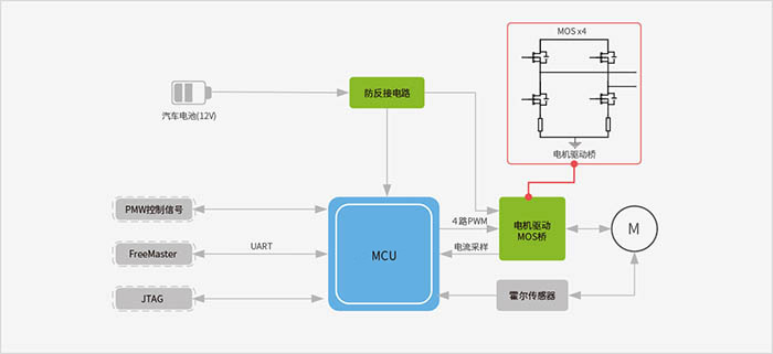
- No external power management IC required - the integrated power management module supplies both internal and external rails
- No external MOSFET driver IC required - gate drive units are integrated
- High-voltage input interface; PWM can be fed in through the LIN interface with no external level-shifting circuit
- The EVDD pin of the MCU can power the Hall sensor
- Minimal component count: 4 H-bridge MOSFETs, which in practice can be implemented with just two Dual Die packaged N-MOS devices
- 1 reverse-polarity protection MOSFET; alternative reverse-protection circuits can be designed to customer requirements
- 1 Hall sensor for sensing the motor rotor position
Functional Block Diagram